This website uses cookies primarily for visitor analytics. Certain pages will ask you to fill in contact details to receive additional information. On these pages you have the option of having the site log your details for future visits. Indicating you want the site to remember your details will place a cookie on your device. To view our full cookie policy, please click here. You can also view it at any time by going to our Contact Us page.
(Click here to view article in digital edition) High Intensity Aviation Obstruction Light

The most common and widespread regulations are the ICAO (International Civil Aviation Organization, a United Nations agency) and the FAA (Federal Aviation Administration, an agency of the United States Department of Transportation).
In the oil & gas sector, three types of signalling lamps are mainly used for the extension and height of obstacles: the low intensity type B and the medium intensity types A and B.
Type B low intensity obstacle warning lights are intended for buildings with low extension and an above ground height below 45 metres (148ft). When the use of type B low intensity obstacle warning lights is inadequate and a special warning is required, medium intensity obstacle signals should be installed instead.
Type A and B medium intensity obstacle warning lights should be used when the object has significant extension or its height above the level of the surrounding area is greater than 45 metres (148ft). Type A medium intensity obstacle warning lights should be used alone, while type B medium intensity warning lights should be used alone or in combination with type B low intensity obstacle warning lights. The flow chart in Figure 1 visually represents when to use each type of signalling equipment.
Type B medium intensity aircraft warning lights are only turned on at night because during the day the obstacle is highlighted by ICAO painting (equal length stripes of red/orange and white paint along an object’s length). Type A medium intensity lights are intended for lighting obstacles without ICAO painting. During the day they remain on with maximum power (20,000 cd) to highlight the obstacle against the daylight background.
Signalling levels and the number of signalling lights for each level
When warning lights are positioned at the top of an object, they must be positioned as close to the top as possible. In the case of cooling towers or other structures with a similar function, the upper obstacle warning lights should be positioned slightly below the top in order to minimise the possibility of smoke contamination.
Where an obstacle is signalled by type A medium intensity aircraft warning lights and the upper part of the obstacle is more than 105 metres (344ft) above ground level or the tops of surrounding buildings, then additional signal lights must be provided at interspersed levels.
These additional lights should be spaced, as far as possible, between the upper lights and the ground level (or at the level of surrounding buildings' rooftops) with a spacing not exceeding 105 metres (344ft).
Where an obstacle requires type B medium intensity aircraft warning lights and the upper part of the object is more than 45 metres (148ft) above ground level or the tops of surrounding buildings, additional signal lights must again be provided at interspersed levels. These additional lights must alternate between type B low intensity warning lights and type B medium intensity warning lights. They must also be spaced as equally as possible between the upper lights and the ground floor or from where the tops of neighbouring buildings are with a spacing not exceeding 52 metres (171ft).
In the oil & gas sector where lattice structures, smokestacks, chimneys, cooling towers, or large tanks are common, the number of warning lights required for each level is typically 3 or 4 light points spaced in the horizontal plane (every 120° or 90°).
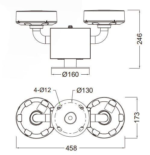
The FAA regulations require the avoidance of any interruption to a safety signal which, if it occurs, must be corrected as soon as possible. Beyond the specific regulation, it is common practice to include redundancy into a signalling lamp system. This is where so-called dual systems (Figure 2) equipped with a main lamp and an emergency lamp are useful. Fault management is then controlled by the control panel of the aircraft warning light system.
Cortem Group has been designing and manufacturing electrical equipment for hazardous areas since 1968. Thanks to continuous technical innovation, it can provide a whole range of products to meet all onshore and offshore applications.
Print this page | E-mail this page

White Heliport Flood Light © 2024 IML Group PLC. All rights reserved.